UNIT 2: Entity Relationship Data Model
Introduction,Benefits of Data Modeling, Types of Models, Phases of Database Modeling, The Entity Relationship (ER) Model, Generalization,Specialization and Aggregation,Extended Entity Relationship (EER) Model.
===================================
1 ) Introduction :
1) In ER modeling, the structure for a database is portrayed as a diagram, called an entity-relationship diagram (or ER diagram), that resembles the graphical breakdown of a sentence into its grammatical parts. Entities are rendered as points, polygons, circles, or ovals
* What is an entity relationship model?
An entity relationship model, also called an entity-relationship (ER) diagram, is a graphical representation of entities and their relationships to each other, typically used in computing in regard to the organization of data within databases or information systems.
2) Types of Model
A Database model defines the logical design of data. The model describes the relationships between different parts of the data. Historically, in database design, three models are commonly used. They are,
- Hierarchical Model
- Network Model
- Relational Model
Hierarchical Model :-
In this model each entity has only one parent but can have several children . At the top of hierarchy there is only one entity which is called Root.

Network Model
In the network model, entities are organised in a graph,in which some entities can be accessed through several path


Phases of Database Modeling

3) Conceptual Design
Once all the requirements have been collected and analyzed, the next step is to create a conceptual schema for the database, using a high level conceptual data model. This phase is called conceptual design.The result of this phase is an Entity-Relationship (ER) diagram or UML class diagram. It is a high-level data model of the specific application area. It describes how different entities (objects, items) are related to each other. It also describes what attributes (features) each entity has. It includes the definitions of all the concepts (entities, attributes) of the application area. During or after the conceptual shema design, the basic data model operations can be used to specify the high-level user operations identified during the functional analysis. This also serves to confirm that the conceptual schema meets all the indenfied functional requirements.
4) Logical Design
The result of the logical design phase (or data model mapping phase) is a set of relation shcemas. The ER diagram or class diagram is the basis for these relation schemas.To create the relation shemas is quite a mechanical operation. There are rules how the ER model or class diagram is transferred to relation shemas.
The relation schemas are the basis for table definitions. In this phase (if not done in previous phase) the primary keys and foreign keys are defined.
5) Physical Design
The goal of the last phase of database design, physical design, is to implement the database. At this phase one must know which database management system (DBMS) is used. For example, different DBMS's have different names for datatypes and have different datatypes.The SQL clauses to create the database are written. The idexes, the integrity constraints (rules) and the users' access rights are defined.6) E-R Diagram
ER-Diagram is a visual representation of data that describes how data is related to each other.
7) Symbols and Notations

8) Components of E-R Diagram
The E-R diagram has three main components
1) Entity
An Entity can be any object, place, person or class. In E-R Diagram, an entity is represented using rectangles. Consider an example of an Organisation. Employee, Manager, Department, Product and many more can be taken as entities from an Organisation.
Weak Entity
Weak entity is an entity that depends on another entity. Weak entity doen't have key attribute of their own. Double rectangle represents weak entity.2) Attribute
An Attribute describes a property or characterstic of an entity. For example, Name, Age, Address etc can be attributes of a Student. An attribute is represented using eclipse.
Key Attribute
Key attribute represents the main characterstic of an Entity. It is used to represent Primary key. Ellipse with underlying lines represent Key Attribute.
Composite Attribute
An attribute can also have their own attributes. These attributes are known as Composite attribute.
3) Relationship
A Relationship describes relations between entities. Relationship is represented using diamonds.- Binary Relationship
- Recursive Relationship
- Ternary Relationship
Binary Relationship
Binary Relationship means relation between two Entities. This is further divided into three types.One to One : This type of relationship is rarely seen in real world.
 The above example describes that one student can enroll only for one
course and a course will also have only one Student. This is not what
you will usually see in relationship.
The above example describes that one student can enroll only for one
course and a course will also have only one Student. This is not what
you will usually see in relationship.
One to Many : It reflects business rule that one entity is
associated with many number of same entity. The example for this
relation might sound a little weird, but this menas that one student can
enroll to many courses, but one course will have one Student.
 The arrows in the diagram describes that one student can enroll for only one course.
Many to One : It reflects business rule that many entities can be associated with just one entity. For example, Student enrolls for only one Course but a Course can have many Students.
Many to Many :
- The above diagram represents that many students can enroll for more than one courses.
Recursive Relationship
When an Entity is related with itself it is known as Recursive Relationship.
Ternary Relationship Relationship of degree three is called Ternary relationship.
*** Generalization *****
Generalization is a bottom-up approach in which two lower level entities combine to form a higher level entity. In generalization, the higher level entity can also combine with other lower level entity to make further higher level entity.
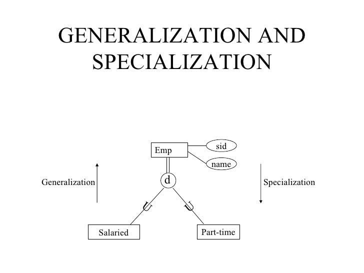
********* Specialization ************


********** Aggregration ******************************
Aggregration is a process when relation between two entity is treated as a single entity. Here the relation between Center and Course, is acting as an Entity in relation with Visitor.

******* Enhanced ER (EER) model ******************
1) Created to design more accurate database schemas
2)Reflect the data properties and constraints more precisely
3) More complex requirements than traditional applications
4) EER model includes all modeling concepts of the ER model
5) In addition, EER includes:
1) Subclasses and superclasses
2) Specialization and generalization
3) Category or union type
4) Attribute and relationship inheritance
5) Diagrammatic technique for displaying these concepts in an EER schema
Example : EER


No comments:
Post a Comment